LED Grow Lights With Best Spectrum & Solution For High Yield of Crops!
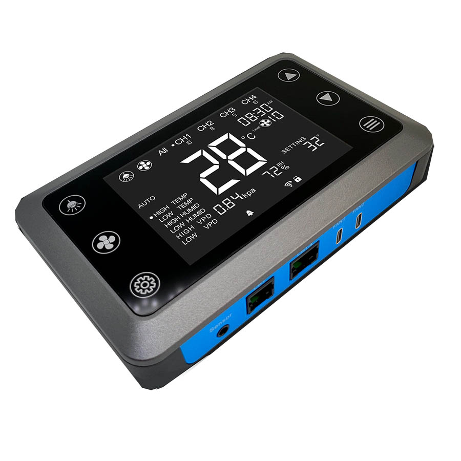
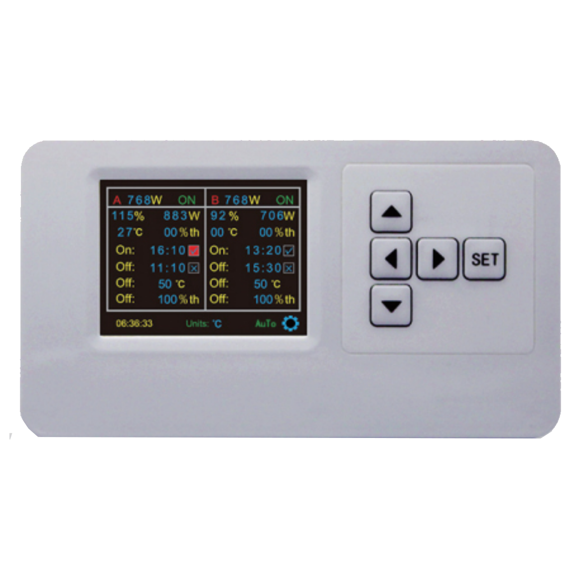
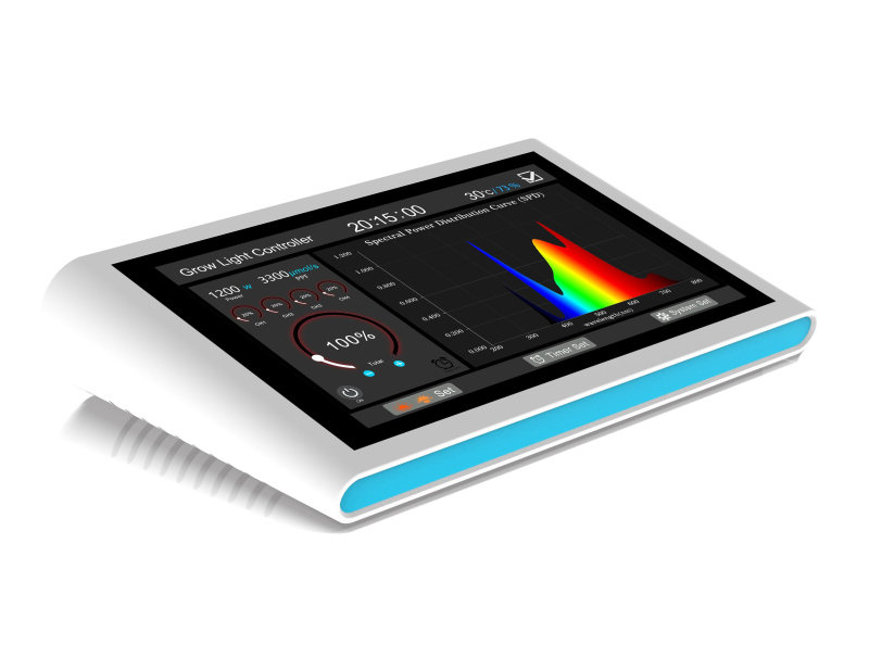
Multi-Channels DIM Controller
Connection Diagram:
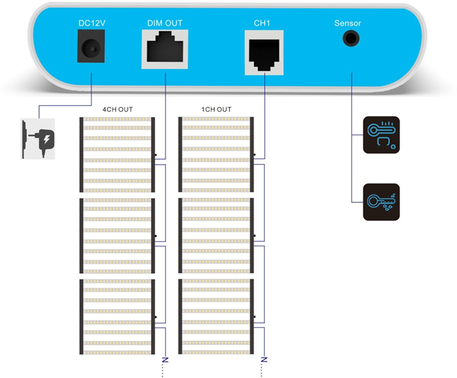
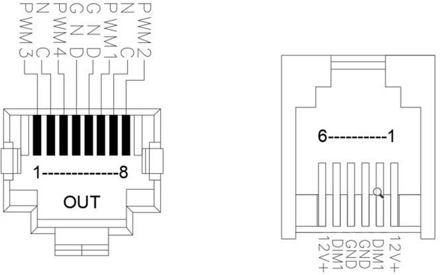
Interface Definition:
1. Electrical Requirement
1.1 Input Requirement
1-1-1 Input Voltage
Normal Voltage: 12V±5%
1--1-2 Input Current
0.5-1Arms
1.2 Output Requirement
1-2-1 PWM signal amplitude value
10V±5%
duty cycle 0%-100%
1-2-2 Analog signal 0-10
1-2-3 Interface definition
Interface | MODEL / parameter |
Signal output | OUT RJ-45 8P8C*1/RJ14 6P6C*1 (The definition can be found in the attached diagram) |
Sensor signal input | Audio seat PJ393*1 |
DC IN | DC5.5*2.1 |
1-2-4 Standby Power
Standby power less than 0.1W
2. Enviroment Requirements
2-1 Termperature
Operation: 0°C to 25°C
2-2 Storage: 10%-95%
3. Reliability
3-1 Mean Time Between Failures (MTBF)
The controller shall be designed and produced to have a Mean Time Between Failures(MTBF) of 20, 000 operating hours.

Connection Diagram:

Interface Definition:

1. Electrical Requirement
1.1 Input Requirement
1-1-1 Input Voltage
Normal Voltage: 12V±5%
1--1-2 Input Current
0.5-1Arms
1.2 Output Requirement
1-2-1 PWM signal amplitude value
10V±5%
duty cycle 0%-100%
1-2-2 Analog signal 0-10
1-2-3 Interface definition
Interface | MODEL / parameter |
Signal output | OUT RJ-45 8P8C*1/RJ14 6P6C*1 (The definition can be found in the attached diagram) |
Sensor signal input | Audio seat PJ393*1 |
DC IN | DC5.5*2.1 |
1-2-4 Standby Power
Standby power less than 0.1W
2. Enviroment Requirements
2-1 Termperature
Operation: 0°C to 25°C
2-2 Storage: 10%-95%
3. Reliability
3-1 Mean Time Between Failures (MTBF)
The controller shall be designed and produced to have a Mean Time Between Failures(MTBF) of 20, 000 operating hours.


